What are the problems with the use of Andel turbine flowmeters in industrial boiler heat balance testing?
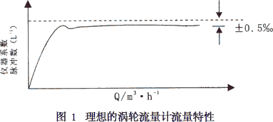
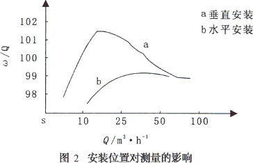
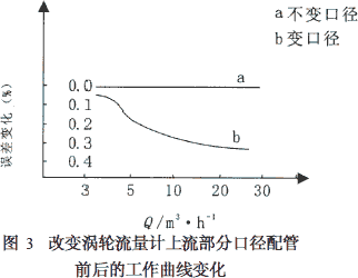
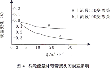
Carrying out the thermal balance test of industrial furnaces and kiln, the economic benefits of mastering the thermal energy utilization of industrial furnaces and kiln, improving product quality, reducing energy consumption and reducing costs for enterprises are undoubtedly huge. In the actual test process, the turbine flowmeter is first selected in the industrial boiler heat balance test because of its high precision, wide measuring range, high withstand voltage and digital signal output. In this paper, some problems of turbine flowmeter used in industrial boiler heat balance test are discussed and summarized. In the actual situation of industrial boilers, limited to various conditions, the feed water of industrial boilers is generally a batch water supply mode that changes with time, which determines the flow in the main pipeline of the boiler water. The flow of the body, that is, the flow of water, usually manifests as a turbulent flow process, that is, the flow of water in the pipes of an industrial boiler flows in an irregular side while mixing, and accurate measurement of the feed water flow and temperature of the industrial boiler is correct. It is critical to analyze the results of the heat balance test. Turbine flowmeters are due to the digital signal output, which is sensitive enough to accurately and punctually respond to turbulent changes in water flow. In a period of time, the flow rate of the water pipe of the industrial boiler is the integral of the cross-sectional area F of the pipe, that is, Q=∫FVDF, and the flowmeter of other principles is difficult to achieve the high precision of the turbine flowmeter. 1 Structure of the turbine flowmeter The turbine flowmeter structure consists of a turbine, a bearing, a preamplifier, a signal receiver, and the like. The flow of measuring fluid from the inlet of the turbine flow meter housing causes the turbine supported by the bearing to rotate at an angular velocity proportional to the instantaneous flow rate. The number of turbine revolutions is detected by an electromagnetic induction sensing coil generated outside the casing and the turbine. After the electrical signal of the sensing coil is amplified and shaped by the preamplifier, the pulse signal proportional to the flow rate is transmitted to the signal receiver, thereby displaying the instantaneous and cumulative flow rates. 2 Turbine flowmeter characteristics The main metering characteristic of the turbine flowmeter is the characteristic of the relationship between the flow rate Q and the indicated value, that is, the flow coefficient. The flow characteristics of an ideal turbine flow meter are shown in Figure 1. It can be seen from Fig. 1 that the flow coefficient of the turbine flowmeter always maintains a certain digital value regardless of the flow rate within a certain flow range. Under this flow characteristic indication value, the cumulative instantaneous flow error can generally be made zero. When the flowmeter starts to limit the flow from zero to a large change, the flow characteristic is unstable, that is, when the flow error is controlled within a certain range, the flow must be above a certain amount, which is the most different. The generality of the principle type of flow meter. The range of transformation shown in Figure 1 is within ±5‰. That is to say, the instrument variation range is within ±5‰. When using it, it should be noted that for a turbine flowmeter, the inherent flow coefficient is the flow characteristic at the factory temperature or at the standard temperature when the instrument is calibrated. When used in practical situations, especially For the industrial boiler heat balance test, it is also possible that the actual fluid used is the high temperature fluid after the waste heat of the economizer. Therefore, in order to ensure the accuracy of the heat balance test, special attention should be paid to the austenitic stainless steel casing material and the turbine flowmeter. The size of the internal components varies with temperature, so the true flow coefficient above the meter calibration temperature is: In the above formula: K-0: the flow rate coefficient of the verified flow meter; 3 use of turbine flowmeter (1) Model selection. Although the turbine flowmeter has the advantage of a wide measuring range, when the thermal balance test of the industrial boiler is performed, the model of the flowmeter should be correctly selected according to the size of the industrial boiler load. Generally, the diameter of the turbine flowmeter should be consistent with the original water inlet pipe on the site. More importantly, the large flow rate of the flowmeter is consistent with the large flow of the industrial boiler, especially the rated load of the industrial boiler. That is, the inflow of the industrial boiler per unit time, and whether the instantaneous flow of the pump exceeds the instantaneous flow rate per unit time of the turbine flow meter. The measuring range of the turbine flowmeter is selected to work in the large linear flow rate of the Zui. Generally, in order to accurately measure, the instantaneous large flow rate can be controlled below 70% of the large linear flow of the Zui, and the accurate measurement of the turbine flowmeter can be ensured. (2) Correct installation. In industrial boiler heat balance testing, the installation and piping of turbine flowmeters is an extremely important part. Practice has proved that due to various reasons, the calculation result after Zui is too large, which is due to the incorrect use of the installation results. In addition to various human error factors, the random installation causes the fluid flow at both ends of the turbine flowmeter to increase, and the Reynolds number of the fluid increases, which relatively reduces the accuracy of the turbine flowmeter. To install the turbine flowmeter, first avoid the piping vibration occasion, pay attention to the place where the piping is stressed, and pay attention to the expansion of the piping with the temperature rise to deform the casing, resulting in measurement error. The second is the protection of the circuit, mainly the protection of the preamplifier, should be avoided as much as possible to cause it to be affected by strong radiation and other electrical equipment magnetic field on the sensing line 而. Although the installation position of the turbine flowmeter can be selected from horizontal tilt or even vertical position, the working curve will change depending on the installation position, as shown in Fig. 2, so the general installation position of the horizontal state is good. (3) Piping points The flow characteristics of the turbine flowmeter determine that its working curve is affected by the pipelines before and after the flowmeter. Therefore, it is required that the upstream part of the turbine flowmeter must adopt a long straight pipe method, which is to maintain the uniformity of the fluid turbulence. Laminar flow. It is generally required that the straight pipe length in the upstream portion is 15D or more (D is the diameter of the turbine flow meter). The length of the straight pipe in the downstream part is 4D or more, and the pipe diameter and the turbine flow meter should be the same. In fact, the influence of the turbine flowmeter characteristic is the existence of the return flow in the pipeline. Therefore, the length of the upstream part should not be changed according to the state of the earlier piping, because the variation of the curved section and the diameter of the pipeline affects the velocity velocity distribution and the existence of the swirling flow. It is also the main reason that affects the measurement accuracy of turbine flowmeters, especially the influence on turbulence is large. Fig. 3 is a view showing changes in the working curve of the piping of the upstream portion of the turbine flowmeter whose diameter is changed. It can be seen from Fig. 3 that in the case of the upstream end variable diameter, the error curve of the turbine flowmeter changes in a negative direction. As the unit flow rate increases, the surface indication value of the flowmeter will be smaller than the actual passing. The volume of the fluid, which will partially affect the thermal efficiency of the industrial boiler, is calculated to be significant for a test cycle of 4h. It can be seen from Fig. 4 that the influence of the turbine flowmeter characteristic is that the swirling flow in the flow exists, so that the measurement result shows a negative value, which is due to the change of the diameter of the curved pipe, which causes the turbulence phenomenon of the fluid flow to increase. The Reynolds number of the fluid is large. In order to eliminate this swirl in the piping, a rectifier composed of a bundle of conduits is installed in the pipeline. The rectifier is actually a plurality of conduits parallel to the pipeline. The rectifier is used in the field and is rarely used in the domestic field. Mainly used in laboratory settings. At the same time, when installing the turbine flowmeter on site, it is especially important that the inlet flange gasket of the flowmeter must not protrude, and there should be no protruding parts in the connecting pipe section. When the author conducted an industrial boiler heat balance test at a factory in Xianyang, the gasket was protruded because the installer did not pay attention, so that the turbine flowmeter clearly showed the number of faults. In addition, it should be noted that the flowmeter shut-off valve must be installed in the upstream part, and in the upstream part, the valve must be fully opened. The above measures are taken to prevent the turbine flow meter from flowing up. (4) Precautions for wiring The general preamplifier sensing cable is shielded from the outside because it avoids inductive noise from the outside. The signal receiver should also be shielded from ground. At the same time, the signal transmission cable can't be close to the power line, and it can't be paralleled. Jiangsu Andel Automation Instrument Co., Ltd. As a dedicated Life Vest manufacturer proudly based in China, we specialize in crafting superior safety gear for aquatic environments. Our product range includes the Water Rapids Life Jacket, the 190N Rescue Buoyancy Vest, and the Outdoor Rafting Life Vest, each designed to provide exceptional protection and comfort. The Water Rapids Life Jacket is engineered for those navigating the most turbulent waters. Its robust construction and buoyancy ensure safety in fast-flowing rivers, offering peace of mind to adventurers and professionals alike. Our 190N Rescue Buoyancy Vest is a high-performance piece of equipment, ideal for rescue operations. With a buoyancy rating of 190N, it offers unparalleled safety, ensuring that rescuers can operate with confidence in challenging water rescue scenarios. For outdoor enthusiasts, the Outdoor Rafting Life Vest is a must-have. Lightweight and adjustable, it provides both safety and freedom of movement during rafting trips. Its bright colors enhance visibility, making it an essential item for any water-based outdoor activity. Each vest is designed with the highest standards of quality and safety in mind. We use durable materials and advanced manufacturing techniques to ensure that our life vests can withstand the rigors of water sports and rescue operations. As your trusted partner in aquatic safety, we invite you to explore our full range of life vests. Whether you're a seasoned professional or a recreational water sports enthusiast, our vests will provide the safety and confidence you need to enjoy your water-based activities to the fullest. Contact us today to learn more about how our life vests can meet your safety needs. Life Vest,Water Rapids Life Jacket,190N Rescue Buoyancy Vest,Outdoor Rafting Life Vest Henan Lukewei Road Machinery Manufacturing Co.,Ltd , https://www.lkwmachinery.com

K-: the flow coefficient of the actual flow meter used;
T0: the standard temperature of the flow meter at the time of verification;
t: the fluid temperature of the flow meter in actual use;
βR: the coefficient of temperature expansion of the turbine material;
βH: The coefficient of thermal expansion of the casing material. 

The effect on the measurement error in the case of a bent pipe joint is shown in Fig. 4. 