Graphic method of forklift angle error
Graphic method of forklift angle error Zhejiang Jiali Technology Co., Ltd. Han Jifeng The corner error analysis is an indispensable work in the design of the steering mechanism. The small angle error can improve the transmission efficiency of the mechanism, realize the approximate concentric circle rolling of the steering wheel inside and outside the steering process, and reduce the wear of the wheel tire. At present, most of the steering mechanisms of counterbalanced forklifts (hereinafter referred to as forklifts) use through-type transverse cylinders. The analysis of the angle error is generally divided into calculation method or drawing method. The formula for calculating the actual corner in the calculation method is more complicated, and the hand work is complicated. The graph error is too large to grasp accurate data. The application of CAD provides an accurate and simple tool for the analysis of corner error in the mapping method. This paper introduces the mapping method using CAXA software for corner analysis. The general steps are as follows: 7. The angle between the actual inner corner line corresponding to each outer corner bisector and the theoretical inner corner line is the corner error, and the larger angle values ​​are marked by the size, which can be viewed directly from the figure. The value of the maximum corner error and its corresponding inner and outer corner values ​​are used to determine whether the mechanism meets the design requirements. In this example, the maximum corner error value is 1.97°, which occurs when the outer corner is 39.27° and the inner corner is 50.65°, which fully meets the design requirements of the corner error less than 5°. Oil Casing,Anti Corrosion Tubing,Carbon Pipe Steel Antiseptic,Oil Casing Tubing Antiseptic Shandong Shifeng Metal Products Co., Ltd. , https://www.qfgygs.com
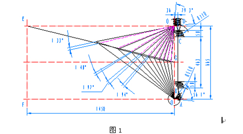
1. Firstly, the geometric model of the steering trapezoid and the theoretical characteristic curves of the front and rear axes and the inner and outer corners are drawn. Figure 1 polygon OABCDO1 is a schematic diagram of the steering mechanism of a forklift, symmetric along the longitudinal axis of the forklift, where O, O1 is the left and right steering wheel rotation center, AB, CD is the connecting rod, BC is the connecting hole spacing of the transverse cylinder, round O, circle O1 is the trajectory circle of the knuckle arm connecting hole, EF is the front axis center line, and EG is the corner theoretical characteristic line.
2. Take the unilateral stroke S of the transverse cylinder (S=58 in Fig. 1), and take the point B as the starting point on the BC, taking the intercept point as the center and the AB length (R=110 in Fig. 1) as the radius on the circle O. Obtain the intersection point, and the line connecting the point and the center O forms an angle with the OA (the angle of 56.1° in Fig. 1), which is the maximum outer corner. The angle is equally divided into several parts using CAXA's “Line-Angle Line†command. In this example, 10 equal parts are used. In practical applications, the angle is subdivided as much as possible, and the bisector is formed into an intersection with the circle O.
3. Select the angle line and boundary line made in the previous step, and use the "Rotation - Start End Point - Copy" command to make the group line take O as the base point, point A as the starting point, and circle O and OO1. Rotate the copy counterclockwise for the end point, and then use the "edge" method to make the set of lines form an intersection with the EG line. Starting from point A, the angle is bisector, the boundary line is the starting point of the circle O, and the arc is drawn with the length of AB as the radius, so that each arc forms an intersection with BC. 
4. The above-mentioned arcs are moved by the "translation-copy" in the BC direction by BC length (463 in Fig. 1), and form an intersection with the BC extension line, starting from point C, with C point and each intersection as the center. The arc is sequentially circled by CD, so that each arc has an intersection with the circle O1, and the intersection points and the center O1 form a set of fan-shaped straight lines, which is the actual inner corner line, and the angle between the two boundary fan-shaped lines (ie, the figure) The 79.3° angle in 1 is the maximum internal rotation angle.
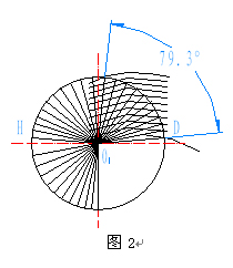
5. Copy the above-mentioned actual inner corner group with the OO1 line as the symmetry axis, as shown in Figure 2, point D to the H point, and use the "Rotation - Start End Point - Rotate" command to set the line. Take O1 as the base point, start with H point, rotate counterclockwise with the intersection of circle O1 and OO1 as the end point (rotation copy is used for the display process in Figure 2), use the "edge" command to make the line and EG line, outside The corner bisector forms an intersection.
6. The intersection of the inner and outer corner lines is sequentially connected by a spline curve to form a curve near the EG in Fig. 1, which is the actual corner characteristic curve. The intersection between O1 and the outer corner bisector and the EG line is connected. For the sake of distinction, the set of lines can be set as a layer line with different colors and lines (dashed lines in Fig. 1). These lines are theoretical inner corners. line. 
It should be noted that the maximum error value of the corner obtained by the drawing method is the maximum value of the selected equal angle, which is an approximation for the entire corner range. However, in the case where the equiangulation angle is small enough (2-5°), the maximum error value obtained is sufficient for the design analysis, and the mapping method can visually see the range in which the maximum corner error occurs and its Trends in the range of corners.
In the design of forklifts, in order to facilitate the production organization, a kind of steering axle is often used on several products with different specifications and different wheelbases. At this time, the front axis and EF line in the above figure are theoretically deleted from the inner corner line. Draw and make the outer corner bisector intersect with EF and draw a new theoretical inner corner. It is only necessary to repeat step 7 of the above process, and the angle error of the steering mechanism at different wheelbases can be easily obtained. For example, in this example, when the steering axle is used for a forklift with a wheelbase of 1350, the maximum corner error value is 3.21°, which occurs when the outer corner is 44.9° and the inner corner is 59.9°, so the method is especially useful in practical applications. The serial design is extremely convenient and fast, and it is also more accurate.