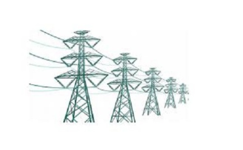
High-voltage radio interference test technology
Reading: The development of industry, more and more demand for electrical energy, indirectly promote the progress of high-pressure technology. The continuous increase in the voltage of the high-voltage power transmission line increases the probability of corona discharge on the wire surface and its discharge. At the same time as corona and discharge, the line will be accompanied by radio interference (or radio noise). The essence of radio interference is a harmful, wide-band electromagnetic wave that occurs during corona and interferes with normal radio communications and harms the environment. 1, the national limit Aluminium fluoride refers to inorganic compounds with the formula AlF₃·xH₂O. They are all colorless solids. Anhydrous AlF₃ is used in the production of aluminium metal. Several occur as minerals. Aluminium Fluoride,Aluminum Fluoride AlF3,Anhydrous Aluminum Fluoride HENAN JINHE INDUSTRY CO.,LTD , https://www.hncarbonblack.com
The radio interference of the high-voltage transmission substation is one of the important indicators of the impact of the high-voltage transmission and transformation project on the surrounding environment. High-voltage radio interference can cause interference and attenuation of radio signals from radios and televisions, affecting their signal quality. In order to protect the normal communication of radio and television signals, the State has issued regulations on radio interference limits for high-voltage line AC overhead transmission lines.
2, measurement methods and requirements
The applicable scope of GB7349-87 GB is: AC power transmission lines and substations with voltage levels of 500KV and below. The measuring frequency range is 0.15-30MHz. The measuring instrument must comply with the specifications of GB6113-85 "Electromagnetic Interference Measuring Instrument". Using the quasi-peak detector, the unit of the effective value of the interference field strength is V/m, and 1 is expressed in dB. V/m is 0 dB using either a whip antenna or a loop antenna with electrical shielding.
Measurement requirements.
2.1 Before Measurement
According to the requirements of the instrument, calibrate the instrument; the relative position of the measurement personnel and the antenna should not affect the measurement reading; other personnel and equipment should be far away from the test site; the height of the loop antenna base should not exceed 2m above the ground, and should be rotated around its axis when measuring. To obtain the maximum reading position, and record its position; whip antenna erection should be specified by the manufacturer; reference measurement frequency of 0.5MHz, 0.5MHz recommended? Measurements are within 10%, but 1MHz can also be used. Since the standing wave may appear on the line, the single frequency measured by the substation is not representative. Therefore, multiple frequencies should be measured within the interference band and a corresponding curve should be drawn; the measurement can be performed at or near the following frequencies; 0.15, 0.25, 0.5, 1.0, 1.5, 3.0, 6.0, 10, 15, 30 MHz, etc.
2.2 Measurement position
The location of the measurement was chosen where the terrain is relatively flat, away from tall buildings and trees, and where there are no other wires, communication lines, or broadcast lines, the electromagnetic environment (background) level is at least 6 dB lower than the radio interference from the measured object. Transmission line: The measurement point should be near the center of the span and 10km from the line terminal. If the conditions are limited, it should be no less than 2km. The measurement point should be far from the line transposition, intersection, corner and other points, but in the case of interference When conducting investigations, this is not a limitation. The measuring point distance should be located 20m away from the projection of the edge conductor. Substation: The measurement point should be selected on the outside of the highest voltage level of the power distribution device, avoiding the entry and exit lines, not less than three points. There are two measuring distances, one is 20m from the nearest charged projection, and the other is 20m outside the enclosure.
2.3 Measurements
Under certain conditions, the measurement has a stable reading; if the measurement is fluctuating, use a logger record or read a number every half minute and average it for 10 minutes. For the use of different antennas should be recorded and processed separately. Transmission line: Each measurement data should be composed of three locations measured along the line and distributed approximately; Substation: Each measurement is made from the measured data at each measurement point to make the spectrum curve.
2.4 Measurements
The number of measurements n must not be less than 15 and preferably 20 or more.