Analysis of Test Method for Insulation Resistance Absorption Ratio of High Voltage Electrical Equipment
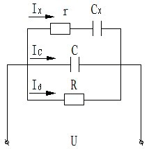
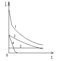
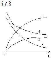
The insulation of electrical equipment is to isolate the conductor from other conductors by the insulating material, thus forming a capacitor. When a direct voltage is applied to the insulation of the electrical equipment, it will produce a decaying charge current, an absorption current, and no time decay. The electric conduction current, the three parts of the current combination is called the leakage current. The equivalent circuit of the insulation resistance test of electrical equipment is shown in Figure 1-1. The charge current in the leakage current attenuates with time, and will quickly fall to zero; the absorption current is due to the accumulation of space charge inside the insulation when the DC voltage is applied, causing the redistribution of the electric field, and this free charge aggregation and flow absorption phenomenon. , Sometimes up to several minutes; Electrically conductive current is a constant current that is inversely proportional to the resistance of the insulating material. Since any insulating material is not absolutely insulated, the electrically conductive current is always present. The test current changes with time as shown in Figure 2. Curve 1 is the leakage current; curve 2 is the absorption current; curve 3 is the electric conduction current; curve 4 is the charging current. Figure 1-3 shows the absorption characteristics of the insulation of the electrical equipment, which reflects the relationship between the current in the good insulation and the insulation. The curves 1 and 2 in the figure show the relationship between the insulation resistance of the insulation and the change of the current. Curves 3 and 4 are bad insulation. The relationship between insulation resistance and current changes. According to the attenuation characteristics of the absorption current of the insulation of the electrical equipment with time, the ratio of the insulation resistance measured at different times (usually the ratio of the insulation resistance values ​​of 60 seconds and 15 seconds) is used as an index for judging the insulation state, which is called absorption. ratio. Absorption ratio K=R60/R15 Force Control System at present, there are several models, suitable for different grinding, polishing work. Force control system of flexible control grinding process, according to the position offset of tolerance of workpiece and subtle moment adjustment, the size of the retention in the set range, to ensure the consistency of surface effect. A perfect fusion of robot and can significantly lower the difficulty of debugging, robot control grinding path, force control system to control the grinding force, grinding force can be quantified, the part tolerance or large deformation of sheet metal, stamping, plastic, etc., still can ensure consistent effect, high production realizability.Flexible grinding system is suitable for the grinding and polishing different work scenarios, apply to the 3 c, auto parts, household sanitary products industry, such as automatic polishing, grinding, especially suitable for curved surface, plane and other equipment arc Angle, body can't implementation artifacts environment. 3C Electronics DFC system, Auto Parts DFC system,Household Sanitary Ware DFC systeme, Traffic And Transportation DFC system DARU Technology (Suzhou) Co., Ltd. , https://www.szconstantforceactuator.com
Figure 1-1 Equivalent Circuit of Insulation Resistance Test of Electrical Equipment 
Figure 1-2 Absorption ratio test current and time diagram 
Figure 1-3 Insulation characteristics of electrical equipment Good relationship between current in insulation and bad insulation
Where: K-absorption ratio;
Insulation resistance at R60-60 seconds;
R15-15 seconds insulation resistance value.
Absorption ratio K can generally reflect the insulation state of the tested device more sensitively, and the insulation performance is not good, especially when the insulation is wet, and the absorption ratio becomes smaller. The well-insulated electrical equipment absorbs more.
Second, the test method of insulation resistance and absorption ratio Insulation resistance of electrical equipment is generally measured using insulation resistance tester (commonly known as the shaking table), insulation resistance tester has three terminal buttons, respectively, "line (L)" end, "grounded (E) “End†and “Protection Ring (G)â€. When the insulation resistance is measured, “L†terminates the part where the electrical equipment is measured and the “E†end is grounded. When measuring, a DC voltage of several hundred to several thousand volts is added. When the ambient humidity is high, leakage current will often occur between the two terminals and the insulator surface, affecting the measurement results, so the protection ring must be connected to eliminate the influence of the surface leakage current. When measuring, terminate “G†to the part that needs to be shielded so that the surface leakage current does not pass through the megohmmeter. The “G†terminal directly flows back to the negative internal power of the Megger to avoid the surface leakage current. The error.
During the test, the relevant power supply of the test object is disconnected first, and the short-circuit grounding is fully discharged. Discharge is also performed after a measurement has been taken to prevent residual charges from causing measurement errors. The megohmmeter should be placed horizontally before the measurement. The handle should be shaken to the rated speed before wiring. At this time, the pointer should refer to “âˆâ€; then reduce the speed, short the “L†and “E†with the wire and point the pointer to “0â€. Then connect the test lead and turn it to the rated speed with no load. When the pointer should be “âˆâ€, then “M†the Megger to the test object, record the time and read the time for 15 seconds and 60 seconds. The value of
Third, the test Note 1. The same rod double-circuit overhead lines or double bus, when one of the road charged, it is not allowed to measure the insulation resistance of the other loop, in order to prevent high voltage damage to the instrument or endanger personal safety.
2. Do not measure overhead lines or electrical equipment connected to overhead lines during thunderstorms.
3. When measuring the object with large capacitance, after reading the value, disconnect the “L†terminal wire from the test object, and then stop shaking the megohmmeter to prevent damage to the instrument due to reverse charging.
4. After the measurement is completed, the short-circuit discharge of the object should be ensured to ensure safety. At the same time, observing the size of the discharge spark and the strength of the sound can also measure the insulation status of the device.