Design of low specific speed centrifugal compressor for vehicle fuel cell
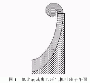
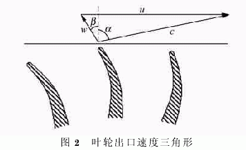
Design of low specific speed centrifugal compressor for vehicle fuel cell Qiu Zhiling  Zheng Xinqian  Zhang Yangjun ( Department of Automotive Engineering, Tsinghua University  Beijing 100084) Abstract: A low-speed centrifugal compressor with on-board fuel cell driven by ordinary high speed (20000r.min-1) motor is designed . The design characteristics of the compressor are summarized , and the internal flow field of the compressor impeller is preliminarily studied by using three-dimensional numerical simulation (CFD) technology . The corresponding characteristic curve and main aerodynamic parameters are obtained. According to the numerical simulation analysis , the designed low-specific-speed centrifugal compressor of the vehicle fuel cell has high efficiency and wide and flat working characteristics . The maximum efficiency of the impeller is 83% at the design speed, the highest pressure ratio is 1.6, and the flow range is At 0.05 to 0.20 kg.s-1 . The design of low specific speed centrifugal compressor, the fuel cell can meet the vehicle air system compressor for the requirements, while avoiding the problem of the required high specific speed centrifugal compressor motor caused by ultra-high speed. Key words: fuel cell ; centrifugal compressor ; low specific speed CLC number: U27 Document code : A Article ID : 1000-0054 (2008) 05-0872-03 Fuel cell vehicles have the advantages of zero emissions, high efficiency, and rapid response . They are the hotspots of research in countries and major automobile companies around the world ; their core is fuel cell technology. Pressurized air is essential for the fuel cell system, its performance has a direct connection. Pressurized fuel cell system has a higher power density and efficiency than the low-pressure fuel cell system, and can improve water balance [1-2]. The specific requirements of the fuel cell air boosting system are : compact size, light weight, air supply without oil and gas pollution, low noise, low maintenance, low cost and high working efficiency [3] . Currently volumetric air compressor is widely used in the fuel cell system applications, is the most typical screw compressor; however, it is difficult to match the work of the turbine, the exhaust gas energy can not be recovered, so that a further energy saving. Recovering exhaust energy, the current can be achieved only by matching the turbine to the centrifugal compressor. Centrifugal compressors also have many advantages such as fast response, long life and high efficiency , and are considered to be one of the most promising boosting methods in the future. At present, the exhaust energy of the fuel cell system is not enough to drive the turbine to drive the compressor , so an auxiliary power source is indispensable. An ultra-high speed ( about 60,000 r.min-1) motor can be used as one of the effective auxiliary power sources. Honeywell is developing a high specific speed centrifugal turbocharger with ultra-high speed motor-assisted drive [4] . The application of this compressor makes the high pressure fuel cell air boosting system smaller and more responsive. Application of ultra-high-speed motor but there are many problems, such as high cost, complicated maintenance, poor stability, require special cooling measures, and there is a high speed rotary shaft load balance the complex problem, which prevent the commercialization of fuel cell engine, whereby Promoting fuel cell vehicles has become a problem [5] . Ordinary high speed ( about 20000 r. min-1) motors avoid the above disadvantages of ultra high speed motors. However, if the centrifugal compressor is still designed with a conventional high specific speed , the pressure ratio can only reach 1.1 to 1.2 [6], which cannot meet the demand for supercharging of the fuel cell system. Therefore, the design must be developed a new centrifugal compressor, it at the same rotational speed and flow conditions, substantial increase in compression ratio, i.e. the design and development of low specific speed centrifugal compressor. Under conditions of low specific speed design a high efficiency, wide operating range of a centrifugal compressor is a great challenge, domestic and few relevant information for reference. In this paper the design software Concept design for a low ratio of the fuel cell vehicle speed centrifugal compressor, and analyzed by flow characteristics NUMECA computational fluid dynamics software, designed to give better performance than the low speed centrifugal compressor. 1 compressor design According to the requirements of the overall design scheme , the main design parameters of the vehicle fuel cell low specific speed compressor are : design speed 20000r.min-1, design pressure ratio 1.5, flow rate 0.1kg.s-1, and must meet certain surge conditions. degree. Under the condition of the rated speed of ordinary high-speed motor of 20000r.min-1 , the pressure ratio needs to be as high as 1.5, and the design is naturally different from the design of the conventional centrifugal compressor. 1.1 low specific speed design Compressor specific speed ( dimension is one ) is defined as Where : ω is the rotational speed , Q is the volumetric flow , and Δ h is the isentropic increase. The specific speed can accurately reflect the function of the compressor. At the same speed , the lower the specific speed , the higher the pressure ratio that can be achieved. Conventional designs typically employ high specific speed, the speed ratio between 0.7 to 1.0, higher efficiency can be obtained. The low specific speed compressor has a high reverse pressure gradient and a large proportion of secondary flow . It is necessary to deeply understand its inherent flow characteristics in order to design a high performance low specific speed centrifugal compressor. 1.2 Impeller one-dimensional design The designed mesa surface shape of the compressor impeller is shown in Fig. 1 . 1) Flow path design features. The impeller inlet section with a smaller radius of curvature profile, and uses a zero angle of attack designed to better accommodate low flow conditions of the fuel cell. Using a more narrow blades, small flow to meet low-speed high-pressure ratio requirements. Because of the characteristics of low specific speed, in the design of an appropriate widening exit width of the impeller, so as to reduce the relative speed of the impeller, thereby reducing the segregation effect. 2) Short bladeless diffuser design. Centrifugal compressors require a diffuser to convert the kinetic energy at the impeller outlet into as much static pressure as possible. For on-board centrifugal compressors , a vaneless diffuser is often used, and the internal fluid flows in an approximate logarithmic curve. For a low specific speed centrifugal compressor impeller , the impeller tangential velocity u at the outlet is very high , but the relative velocity w of the gas flow and the radial flow velocity along the blade are relatively low , resulting in its absolute velocity c and radial. The angle α is large , as shown in Figure 2 . The circumferential flow of the fluid in the vaneless diffuser section is long , the friction loss increases sharply , and reflow is highly likely to occur. In order to reduce or even avoid such losses and improve the gas compression efficiency , a shorter vaneless diffuser is employed. 3) volute design features. Since the air outlet of the impeller in the radial velocity is small, and not flow, so the design uses a lower smaller diameter than the speed centrifugal compressor volute. 1.3 impeller three-dimensional design Three-dimensional modeling using the Axcent module of Concept software . Since the elongated blade and the larger curvature as to reduce the load per unit area on the blade, the blade adopt a method of increasing the wrap angle, while decreasing the relative velocity difference between the face and the back blade, the control structure of the jet flow formed in the end, to improve the state of flow between the blades to reduce diffusion losses. Using the splitter blade to reduce the flow blockage. Impeller axial length as short as possible, to reduce the volume. With 40 ° bend design, to improve efficiency and broaden stable operation range. 2 flow analysis The three-dimensional flow field calculation of the centrifugal compressor impeller uses NUMECA simulation software. The governing equation is a three-dimensional Reynolds mean Navier-Stokes equation. The turbulence model uses the Spalart-Allmaras model. In order to save the calculation workload , the impeller takes 1/10 along the circumference , and contains a splitter vane in the middle , using nearly 300,000 nodes. Imports give a given total temperature, total pressure, speed direction , static pressure extrapolation ; outlet given flow ; periodic boundary conditions are given along the circumference. Numerical Simulation of the rotation speed of the impeller, respectively 20000r.min-1 (design speed), 18000r.min-1, the flow 16000r.min-1, the characteristic curve shown in FIG. It can be seen that at the design speed , the maximum efficiency of the impeller can reach 83%, and the highest pressure ratio can reach 1.6 . The designed centrifugal compressor has a wide and flat working characteristic , which can meet the requirements of wide flow conditions of the vehicle fuel cell. Figure 4 shows the static pressure distribution on the pressure and suction surfaces of the main and splitter blades , where L represents the axial length of the impeller. It can be seen that the splitter blade load is substantially the same as the main blade load , avoiding the mixing loss of the large and small blade airflow at the outlet. Except for the stagnation of the main blade and the splitter blade head edge due to the flow in the 90% section , a static pressure peak appeared , and the static pressure distribution was smooth and no abrupt change. Overall , the blade load distribution is reasonable. Figure 5 shows the absolute velocity vector diagram near the impeller exit. As can be seen, the rotation speed of the circumferential direction is far greater than the radial velocity (due to low flow), so that the vicinity of the impeller exit velocity vector almost parallel to the tangential direction of the impeller, and exactly one-dimensional analysis results of FIG. 2. Thus, we must be very short bladeless diffuser to reduce flow losses in airflow diffuser brought circumferential rotation. 3 conclusions A low specific speed centrifugal compressor for a vehicle fuel cell system was designed . The compressor can be driven by a common high speed motor , which is low in cost, easy to manufacture, long in life and more suitable for low flow conditions. Numerical simulations show that the designed rotational speed is lower than the centrifugal compressor, rated at a normal speed motor design speed 20000r.min-1, the impeller ratio of 1.6, 83% efficiency, the fuel cell can meet the requirement for the compressor. Acknowledgements This work has received strong support from researchers such as Xing Weidong, Zhang Junyue, Zhang Jizhong and He Hong, the key laboratories for diesel engine high-pressure technology , and I would like to thank them. Guangzhou Airy Filter Media Co.,ltd , https://www.gzairy.com


